

Inspirational Quotes


Back in the Day
Search
Portfolio
Work-Related Projects
Working with Cryptotronix
Description
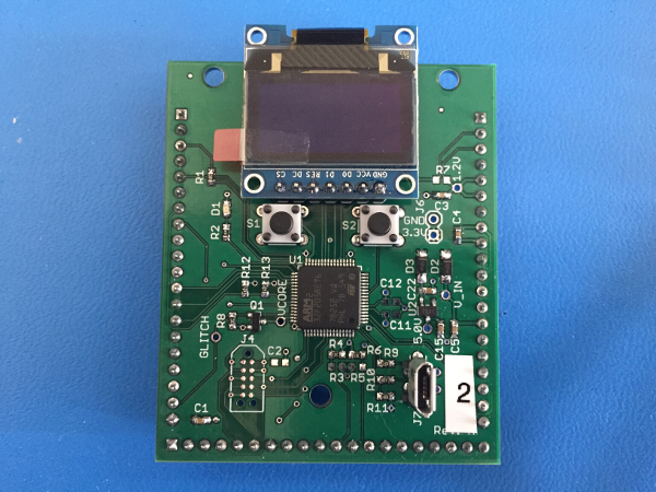
I had a great pleasure meeting Josh and working with him on some of his very exciting projects! Everything started with our trip to DEFCON where we attempted to break Bitcoin hardware wallets. I did not get to talk but I did participate behind the scenes. Check out this talk for more details!
Next, we moved on to multiple board designs for various purposes. I am not going to go into much detail since some of them were pretty specialized. But think cryptography and hardware combined!
And finally, I worked on some FPGA projects. I've done High Level Synthesis, compiled open source Verilog project and modified it to use a different sister crypto algorithm. Furthermore, I designed SoC (System on Chip) that included both custom build and generic IPs. By the way, I've created those custom build IPs. And I wrote C drivers for those projects. A lot of those projects were more of a proof of a concept kind but I really enjoyed working on those! I learned a lot and I feel like my FPGA skills greatly improved after tinkering with those so much.
Contribution
Hardware, Software, Verilog, Firmware, HLS, SoC Design
For the Breaking Bitcoin project, I've designed hardware that technically was a clone of the open source hardware wallet called Trezor. But it was in the shape and form of Chip Whisperer target board. That made hardware attack attempts way more accessible. I have not worked on any attacks. With exception of really simple attack with Arduino. However, Arduino proved to be too slow for such a task. I've also written Python script that would read Trezor pin pad and decode keypad into 3x3 matrix. I've used computer vision library called OpenCV for such a task.
External Resources
Breaking Bitcoin PDF Presentation

|
|
Bolder Automation
Description
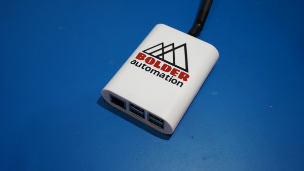
I've got permission to apply the code that I have developed for the Mesh Network project to other industrial automation applications. So I've started working on developing open source system for the general public. There are still quite a few things that need to be done. Also it is more of a part time project as of now. Things might change if I find funding and/or clients. Follow Bolder Automation website for further update on this project.
Some of the pictures bellow have not been posted anywhere but here. Those are part of my research on home automation systems. Home Automation router is also based on Raspberry Pi 3. I've added IR LEDs to it and IR receiver as well as 433 MHz receiver and transmitter that can be used in home automation projects.
Contribution
Hardware, Software, Product Design, Website and impressive stick figure graphic design has been performed by yours truly!
First of all, I modified the code so it functions on any operating system. Next, I've ported our embedded linux environment to Raspberry Pi 3. I had to design hardware to do so. And that is how Bolder Automation Mesh Network Router came to be. I still need to redesign hardware for the Mesh Network Nodes but before I do that I want to fix few more bugs in the system and do some major software improvements. Stay tuned!
External Resources
|
|
Various Hardware Projects
Description
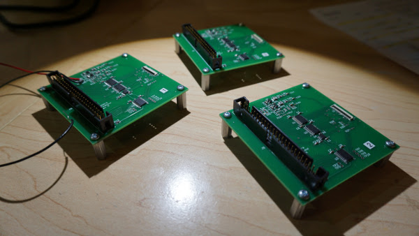
For my last client, I ended up creating multiple little breakout boards, stepper motor driver and fairly complex power board. I won't go into much detail and hope pictures will do the justice.
Contribution
I've developed hardware, created kits, assembled most of the boards and tested those in my lab. I wrote little driver to test functionality of the stepper motor driver board. Firmware for the power board has been past on the firmware engineer at my client's company.
External Resources
|
|
Mesh Network Router GUI
Description
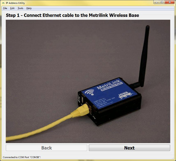
Once web interface for the mesh network has been developed we found that a lot of our users
were struggling setting up ip address of their wireless mesh network router. My client
requested to make a GUI to ease the experience of setting up mesh network system.
GUI had 2 modes - advanced and basic. Funny thing, it was easier to code advanced mode and
basic mode took a bit longer. In advanced mode, user manually selects COM port that Mesh
Network Router is connected to. In basic mode, user presented with the steps and GUI goes
through serial ports and detects what port router is connected too.
Next, user can either modify ip address settings or just look up current settings and finally
test displayed ip address in their web browser.
Contribution
Sole project as far as implementation. Used python and PyQt4 for the GUI. Compiled executable
version using bbfreeze. Also, GUI included gif animations which was pretty neat feature.
Pictures below might give you a bit better idea what this GUI experience would be like!
External Resources
|
|
Mesh Network Software
Description
I roughly described hardware side of this project below. Once hardware was developed I started
writing software. First and foremost, I designed protocol to communicate with the nodes of the system
(aka field units). Next, since those units needed to operate on a single battery for few years, I
updated protocol so the field units operate as a sleepy mesh network. Network that sleeps most
of the time, wakes up at certain intervals and reports to the user.
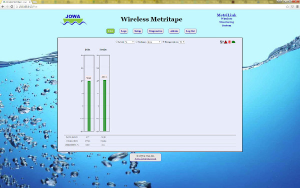
Next, I designed web interface that controlled sensor constants, data output, admins/users, system
settings preferences, Modbus/SNMP settings, alarm settings, diagnostics data, log exports and
import/export of the all the settings listed above.
Another functionality that I forgot to mention is ability to group nodes. Also there is platform
engine behind the scenes to facilitate different hardware, different sensors attached to that
hardware and finally metadata that is used to generate output using sensor parameters and display
it in different units selected by the user. Furthermore, user is capable to generate alarms which can
propagate alarm condition down the line either using Modbus or SNMP protocols.
System wide warning engine has been implemented as well in case one of the nodes fails for any
particular reason. Using system settings it is possible to either enable pop up window or sound
alarm on the web interface.
And lastly, there is a software update engine that can be used to wirelessly update any node,
bridge node (node inside of the embedded computer), software of the embedded computer itself
(aka mesh network router) or all of the above as a bundled procedure.
Contribution
Once again it was a sole project as far as design. I've received a lot of valuable feedback from my
client. I've used python as my main language for the mesh network router. Pybottle as a web server
framework, tornado as web server engine. I've used some libraries to get Modbus and SNMP working.
Obviously, there are way more details. I think pictures might give you a bit better understanding
of the project. Also, my client wrote a lot of manuals and data sheets for the project. I've
documented some of the project and used automatically generated documentation that gets extracted
from the code comments. Furthermore, there is a mechanism to generate pictures describing
classes and relationship between python modules during distribution generation process.
External Resources
|
|
Mesh Network Hardware
Description
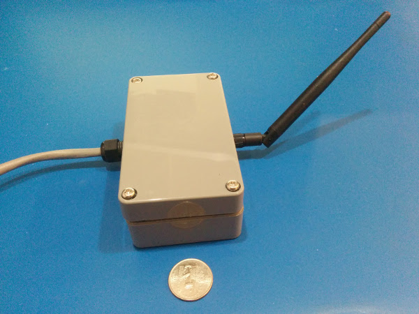
One of my contract jobs was to design mesh network system. Everything started from designing hardware. I've used proprietary module and designed hardware that would connect RF module and external sensor. I've also had couple designs for the small form factor hardware but those were not used in the deployment. We used little embedded linux computer to control all the nodes and display output data via web server interface.
Contribution
Sole project as far as design. I've received a lot of valuable feedback from my client. Also, final board layout was designed by my client, however it was heavily based on my prototype design.
External Resources
|
|
Sonar System Hardware Testing GUI
Description
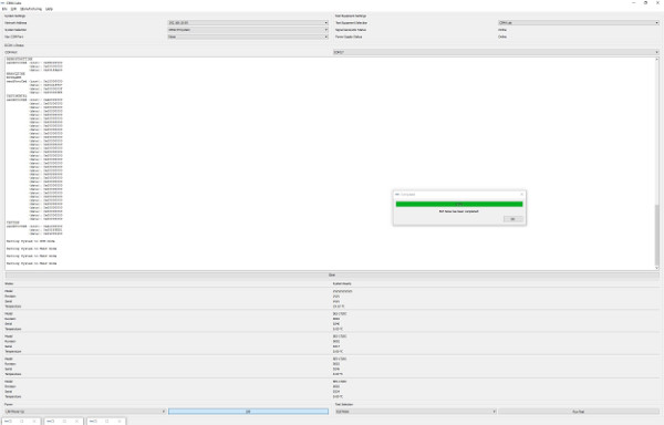
For the system that have been briefly described below, I developed GUI that was intended to
be used during hardware testing. Since system had multiple hardware variants, I designed UDP
protocol encoder and decoder. Protocol for each project (or hardware variant) was described
using native python data types. Incoming traffic was translated into python data structures and
outgoing traffic was encoded from data structures into UDP packets.
Furthermore, I designed library to control the instruments via SCPI protocol,
for this project we needed power supply and signal generator.
Output from each board along with some debugging information was displayed as part of the GUI.
Finally, I designed utilities to store each test setup as well as test themselves, that
controlled instruments, system and output format of the test results.
Contribution
The GUI development was my sole project. I did receive a lot of technical information as far as hardware and overall system operation from my colleagues but it was solo quest as far as implementation. I wrote it in Python, used PyQt4 library to base the GUI, also used pcapy and impacket to parse ethernet traffic, pyserial to output debugging messages, matplotlib to plot output and other python packages. Pictures of the test output were taken during development of the test output plotting engine, so they missing a lot of detail information.
External Resources
There is no further information available on the internet. Thank you for your understanding.
|
|
Sonar System Hardware Design
Description
I can not disclose much detailed information as far as application of this product. For this project our team developed most of the hardware while a lot of the higher level software was produced by our contractee.
Contribution
My contribution consisted mostly of board layouts and schematic creation as well as some FPGA coding. Also, I worked on part selection and some analog circuit simulations. Metal plates for the system were also designed by me. (See below for more information)
External Resources
There is no further information available on the internet. Thank you for your understanding.

|
|
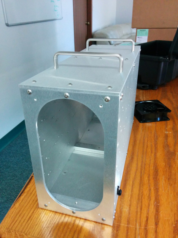
Sonar System Mechanical Design
Description
To keep our system cool and safe from the external noise I designed aluminium enclosure using SolidWorks software. Obviously, our contractee did not use the design in their deployment but it was very helpful during internal hardware testing stages.
Contribution
Solo project. Pretty straight forward design.
External Resources
There is no further information available on the internet. Thank you for your understanding.
|
|
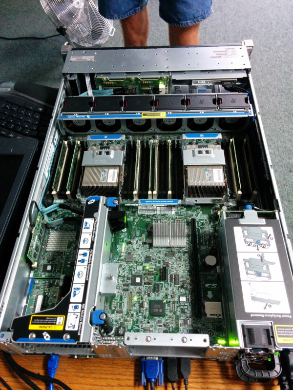
IT Work
Description
I've done some IT work. Setting up server for our company to run colony of the virtual machines. Also, I wrote this virtual machine backup script. Check it out on GitHub.
Contribution
Solo project as well
External Resources
There is no further information available on the internet. Thank you for your understanding.
|
|
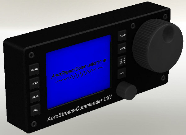
HF SDR(High Frequency Software Defined Radio)
Description
HF SDR is a product developed for the ham radio enthusiasts. The main idea of the product is to allow amateurs radio hobbyists to upgrade from the analog to the digital world and enchase their communication experience. The radio was conveniently designed to work as a stand by unit or in a pair with a PC.
Contribution
I played one of the major roles in this project. The scope of the work that I have done includes hardware development, schematic capture, digital and RF layout, BOM, part selection and testing. Once again, layout was particularly challenging to due to the mechanical constrains of the project. I have used my creativity to the fullest and came up with numerous layout strategies that resulted in highly ergonomic design.
External Resources
Development finished fairly recently and the project is still in a preproduction stage. Information on the web is quite limited. I will provide some external references as soon as they are available.
|
|
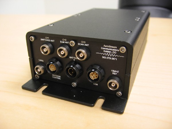
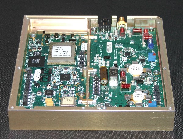
MQR(Miniature Quick Scan Receiver) Phase 3
Description
MQR is software defined radio that is capable of detecting signals up to 3GHz and down to -120dBm of strength. It also has DF and TDOA capabilities. The hardware side of the radio was complex, the radio utilizes 3 channels. The whole hardware spreads out across 6 boards. It is relatively small in size, therefore making the hardware layout more difficult and dense. The software side includes FPGA routine, DSP script and GUI for a PC that controls the radio as well as displays its acquired data.
Contribution
I had a major contribution to this project. I developed most of the hardware for the MQR, did schematic capture, digital and RF layout, BOM, hardware testing and debugging, firmware development and documentation. Development of the RF board was challenging in particular because I had to keep the layout of all the channels identical in order to minimize phase differences. Furthermore, I participated in the mechanical development of the radio and contributed several ideas that were later implemented, helping to further restrict the size of the radio.
External Resources
Development finished fairly recently and the project is still in a preproduction stage. Information on the web is quite limited. I will provide some external references as soon as they are available.
|
|
UL-801 (UniLink)
Description
UL-801 is a powerful software defined radio for the aviation industry. We had to obey strict standards while developing it. The radio had high requirements that we had to fulfill. The radio was intended to use mostly for data via D8PSK modulation scheme.
Contribution
My contribution consisted of hardware development, testing and debugging. Also, I worked on documentation for this project.
External Resources
UL-801 was developed for Universal Avionics. Development was finished up fairly recently and is still in preproduction stage. There is not much information that can be found on the internet. I will provide some external references as soon as it they will be available.
|
|
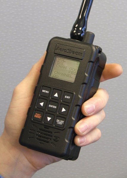
HHx
Description
HHx or Hand Held Receiver/Transmitter is a broadband Software Defined Radio. It's intended to work on multiple bands plus transmit data using FSK. Furthermore, it can be adapted to build a network of radios that will switch stations following base radio. The field of use would be rescue operations. The HHx would allow rescuers to communicate with people, police, medics, military, etc. who currently utilize different bands and different modulation schemes.
Contribution
Most of my contribution to this project was hardware debugging and testing. Once developing was completed, I got to work on quality control and mechanical assembly control.
External Resources
Development was finished up fairly recently and is still in preproduction stage. There is not much information that can be found on the internet. I will provide some external references as soon as it they will be available.
|
|
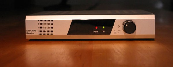
Digital Reading Service Receiver
Description
The basic idea behind the Digital Reading Service Receiver was to create a television set-top box that would pick up the sound portion of the TV channels. It was created for blind people so they can listen to a special audio channel that is transmitted using new digital TV standards.
Contribution
I did not get to develop hardware for this project but I got to debug it as well as ensure that the hardware was functional. The whole software portion of this project was developed by me. Also, our developer's team decided to include my name on the patent application and listed me as a co-inventor of the Digital Reading Service Receiver.
External Resources
|
|
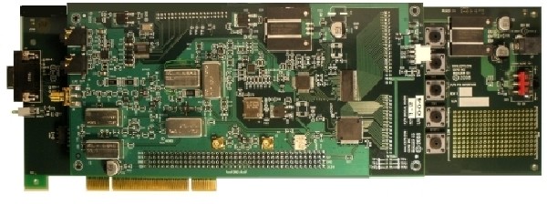
DRK(Digital Radio Kit)
Description
The Digital Radio Kit was an FPGA based project. The scope was to create an FPGA controlled radio that is capable of transmitting and receiving on the FM band. It was also designed to interface with computers via PCI bus.
Contribution
The Digital Radio Kit was an in-house CEPD project that I contributed a lot of my time to. I wrote VHDL code for Xilinx-3E FPGA that controlled most of the hardware on the board. This included the PCI card driver, PLL for the mixers, user interface (buttons and LEDs), audio codec, T/R switch and the RS232 chip. I also contributed to the hardware development and testing.
External Resources
Altera Based DRK Datasheet in PDF
Xilinx Based DRK Datasheet in PDF
Land Seismic Acquisition System
Description
As an Engineering Intern on the CEPD Inc. team, I got to participate in developing every component of the system. This included work on Data Acquisition Units, Transmitters and Offloading/Charging Racks. The basic scheme of the system in use would be the deployment of numerous DAUs and activating them using several transmitters all the while keeping everything on the same clock synchronized by GPS. More detailed information can be found on Ascend Geo's website.
Contribution
My contribution consisted of some hardware development as well as testing numerous components of the system. The project was a perfect introduction to Embedded Systems in a real world application while still working on my degree at CU, Boulder.
External Resources
Interactive System Description
|
|
School-Related and Free-Time Projects
RGB Ball 2
Description
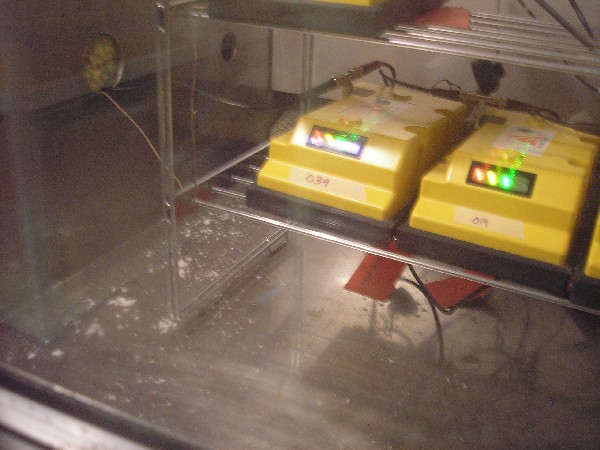
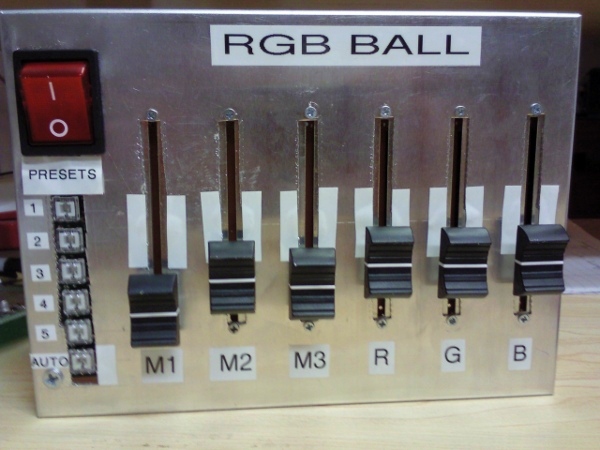
This was one of my free time projects. I guess the goal was to create fully functional product. I did not quite get to that point yet since I had to move to Europe for the grad school but most of the electronics was finished and software written. This project was great learning experience. I spent a lot of time and money but I hope I will be able to finish it one day and it will pay off one way or another in the long run.
Contribution
Technical Details: System was designed to have 2 boards. Main board has 6 potentiometers (3 Motors + 3 LEDs), wireless transmitter with PCB antenna, small 8-bit MCU to control everything and power circuitry charged by 2 AAA batteries. Second board, called motor board, was designed to have wireless receive with PCB antenna, 3-H bridges that would control 3 motors via PWM sequence, 3 opto-isolators to control LEDs, MCU and finally power circuitry providing 3 different voltage levels for the motors. Mechanical side of the project was a big challenge for me since I do not have experience designing such fixtures. But I was able to prove to myself that there is nothing impossible. While working on the project, I've learned SolidWorks to bring my idea to an electronic draft. Next, I've attended mechanical workshop to learn how to transfer idea on paper (or PC) to life. I've learned how to create rubber molds, used 3D printing technology and finally learned CNC machining tools and technique.
External Resources
I would love to write a ton of what goes behind the idea but I thing demonstration would tell you everything without one spoken word. Just follow this link: https://www.youtube.com/watch?v=sO2-tqoyGik
|
|
This Website
Description:
This website's purpose was to introduce myself to potential employers, to a graduate committee and to put my portfolio in an accessible online place. I did not have any web development skills prior to this project and had to learn a lot of new concepts in my free time. Some of these include HTML, CSS, JavaScript, XML, AJAX, PHP and SQL basics. Hopefully, this website will help me to achieve my career goals and show my dedication.
Contribution
This project is solely my creation. I used some code for reference but the website itself was created from scratch. Some of the images that I used here were created by hand and exported in digital format through a scanner.
External Resources
Real Time Digital Media System
Description:
I took this class to finish up my Embedded System Design Certificate in the Spring of 2009. The class introduced me to concepts and insides of Operating Systems, Real-Time Theory, Digital Video and MPEG2 standard, POSIX Threading, Robotic Arm Kinematics, Linux Driver Development, RAID System, and Real-Time Video Streaming.
Contribution
Labs were individual; I successfully completed all laboratory assignments and a final project.
External Resources
Car Monitoring System
Description
The spring of 2008 was my last semester at CU and just like any other student I had to come up with an idea and deliver final project. Our group consisted of 5 teammates. We decided to work on an In-Car Automation and Monitoring System that would provide an alternative to car wiring harness. Our idea was to create our own instrument panel that would communicate to multiple sensors using ZigBee technology.
Contribution
I was one of the leaders on this project. I definitely had more experience in Embedded System design than any of my other teammates because it was my primary area of study. Consequentially, I took more courses that were oriented in that direction. I had some real world experience from my internship at CEPD and this proved to be helpful during the project. My contribution was hardware design of the main terminal (instrument panel) plus most of the firmware for the board. We were using graphic monochrome LCD that I had to write a routine for and a library that would display text and graphics.
External Resources
|
|
DSP Laboratory Projects
Description
This class offered a lot of hands-on experience connected to the DSP field. Most of the students were afraid of taking it because it was very dense and time consuming. I was taking this class concurrently with my senior project. The DSP Lab (ECEN4532) required far more time than my final project. The labs included the following assignments: writing assembly programs for the Motorola 56300 DSP microprocessor, creating counters, experimenting with aliasing, simulation of delay lines, simulating Doppler Shift effect, designing FIR and IFR filters using MatLab and implementing it on DSP, simulating reverberations, signal generation and creating a music score player. Also, the lab had an image processing portion where we used MatLab as the primary tool. The following assignments were completed: color manipulation (grayscale conversion, linear contrast stretching, histogram equalization, gamma correction), implementing image filters such as Blurring, Unsharp Masking and Median Filtering.
Contribution
Laboratory assignments were individual; I have completed all of them successfully.
External Resources
|
|
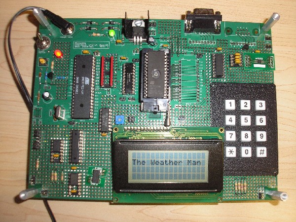
The Weather Man
Description
The Weather Man was my final project for an Embedded System Design class (ECEN 4613) during the fall of 2007. The device used sensors to capture temperature, humidity and atmospheric pressure, relaying them to a histogram. Also, a real time clock on the board of the device would allow the user to set a specific time of start and end to the data acquisition.
Contribution
This class started off with individual labs but was intended to end as 2-person final project. My partner and I decided to use my board as a hardware base for our mutual project. The board was soldered and wire-wrapped by me and was working perfectly thanks to my detail-oriented approach. We added additional hardware components and developed firmware together. The rest of the software that was user-interface was built by me. We passed all of the final project requirements and got excellent grade for it.
External Resources
|
|
